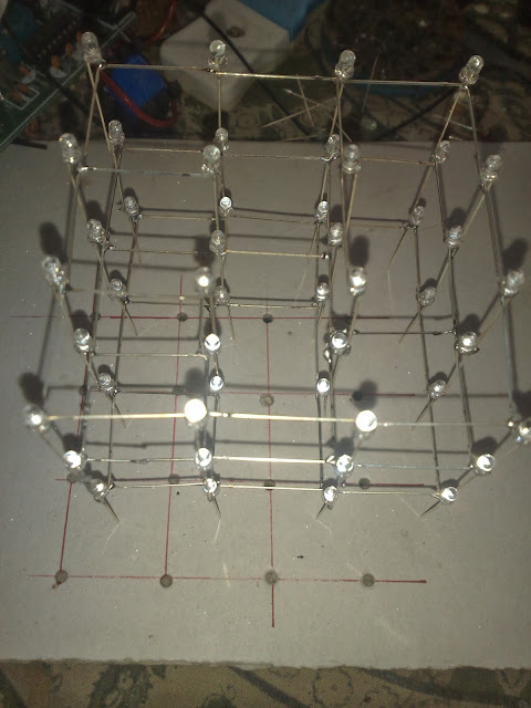
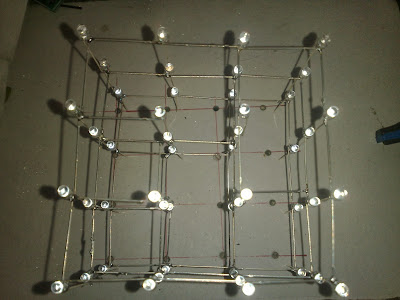
The LED cube is made up from 64 LED's arranged into 4 layers of 16 LED's each. The display itself is multiplexed so instead of requiring 64 connections it requires one to each of the four layers and 16 to each LED in a layer making a total of 20. The cube is refreshed by a software interrupt routine with each layer active for 2 ms so the entire cube is refreshed every 10mS (100Hz). This results in a display with no visible flicker.
EL Botics
Wednesday, September 18, 2013
Sunday, November 18, 2012
Cell Phone Controlled Relay
Now a days all of them are using various types of cell phone in the world. Imagine that from your cell phone you can control a relay which is connected to you home gate lights or other equipment's in the house. So i build a circuit for this application.While calling to someone, if we press any button in the cell phone a tone produced and the receiver can heard.This tone is called DTMF (Dual Tone Multi Frequency).For more about DTMF, see my previous post.The working of the circuit is based on this principle.
Saturday, November 17, 2012
DTMF Decoder
While calling to someone, if we press any button in the cell phone a tone produced and the receiver can heard.This tone is called DTMF (Dual Tone Multi Frequency). DTMF assigns a specific frequency (consisting of two separate tones) to each key so that it can easily be identified by the electronic circuit. The signal generated by the DTMF encoder is a direct algebraic summation, in real time, of the amplitudes of two sine (cosine) waves of different frequencies, i.e., pressing ‘5’ will send a tone made by adding 1336 Hz and 770 Hz to the other end of the line. The tones and assignments in a DTMF system are shown below.
Frequencies
|
1209 Hz
|
1336 Hz
|
1477 Hz
|
1633 Hz
|
697 Hz
|
1
|
2
|
3
|
A
|
770 Hz
|
4
|
5
|
6
|
B
|
852 Hz
|
7
|
8
|
9
|
C
|
941 Hz
|
*
|
0
|
#
|
D
|
An MT8870 series DTMF decoder is used here. All types of the MT8870 series use digital counting techniques to detect and decode all the 16 DTMF tone pairs into a 4-bit code output. The built-in dial tone rejection circuit eliminates the need for pre-filtering. When the input signal given at pin 2 (IN-) in single-ended input configuration is recognised to be effective, the correct 4-bit decode signal of the DTMF tone is transferred to Q1 (pin 11) through Q4 (pin 14) outputs.The circuit is shown below.
3.5mm Headphone Jack
3.5 mm Headphone Jack is a 1/8 inch or 3.5 mm headphone jack is an audio socket that accepts a 3.55 mm male pin or audio plug. A small round connector for accepting the pin-shaped plug from a standard pair of music headphone. Below schematic shows the typical diagram of 3.5mm Headphone Jack.
3.5mm Headphone Jack Schematic Diagram
- 1 – tip : audio out left channel.
- 2 – 1° ring : audio out right channel.
- 3 – 2° ring : microphone line in.
- 4 – 3° ring/sleeve : ground – common for microphone and audio out.
In circuits we only need the Speaker +ve and the speaker ground. For circuit, Tip pin as the 1 and the ring pin as either the right channel out (pin 2) or left channel out (pin 1). The modified schematic diagram of the 3.5 mm Headphone Jack for circuits is below (for electronics application).
Thursday, November 15, 2012
Wednesday, November 14, 2012
4 Channel Led Chaser
This LED chaser display is build around readily available, low cost components.This circuit is easy for build for a beginner in the electronics. The power supply for the chaser circuit is from a 9v battery.The circuit diagram of the chaser is below.
Click the circuit for enlarging.
The NE 555 timer ic and decade counter 4017 is the heart of the circuit. The astable multivibrator built around IC2 produces a clock frequency at its output pin 3. This output is connected to clock pin (pin 14) of the decade counter Cd 4017.The decade counter can count up to 10. But in circuit we only use 4 O\P so the Q4 (pin 10) is connected to the reset (pin 15) of the CD 4017. The output of IC3 advances by one count every second (depending on the time period of astable multivibrator IC2). The VR1 connected between the Pins of IC2 determine the speed of the glowing of the bulb.
Saturday, November 10, 2012
Arduino UNO - R3
This is the new Arduino Uno R3. In addition to all the features of the previous board, the Uno now uses an ATmega16U2 instead of the 8U2 found on the Uno (or the FTDI found on previous generations). This allows for faster transfer rates and more memory. No drivers needed for Linux or Mac (inf file for Windows is needed and included in the Arduino IDE), and the ability to have the Uno show up as a keyboard, mouse, joystick, etc.

Subscribe to:
Comments (Atom)
.jpg)
.jpg)


